![]()
Principles of Operation
Liquid flowing through the unit causes the paddlewheel to spin.
As the magnets embedded in the paddle wheel spin past the sensor, electrical pulses are produced in which the frequency is proportional to the flow rate.
The number of pulses per desired time interval and the K-factor (number of pulses/Gallon) make it is possible to calculate the flow rate and volume passing through the unit.
On board CPU and signal conditioner circuitry perform accurate flow and total computation, digital communication and provide analog 0-5 Vdc or 4-20 mA output signals.
Non-volatile memory stores all hardware specific and ser programmable variables, including flow linearization table. The flow rate can be displayed in 23 different volumetric or ass flow engineering units.
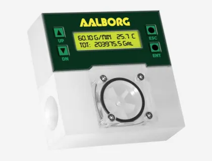
Flow meter parameters and functions can be programmed locally via key pad and LCD* or remotely via the RS-232/RS-485 interface.
PWE flow meters support various functions including : two independently programmable flow totalizers, user programmable low, high or range flow and temperature* alarm, two sets of user programmable optically isolated outputs, self diagnostic alarm, flow pulse output.
Optional local 2x16 LCD* readout with adjustable back light provides flow rate, temperature*, total volume reading in currently selected engineering units, diagnostic events indication and feature a password protected access to the process parameters to ensure against tampering or resetting.